The firmware in firmware/ is C on the Raspberry Pi Pico SDK 2.3.0, for the RP2350B only. It
started as a fork of the pic0rick firmware (0.1.11). Its version is in
firmware/version.yaml and printed by the version command. This page describes
firmware 0.1.16.
firmware/build.sh builds both variants from the same sources. CMake selects one with -DDSP:
stdio build (main.c) |
DSP build (main_dsp.c, -DDSP=ON) |
|
|---|---|---|
| USB | SDK stdio_usb, 2e8a:0009 |
Raw TinyUSB CDC, cafe:4011, serial U4RK0001 |
| Interface | Text console, one command per line | Text commands, OK … / ERR … replies, plus binary U4RK frames |
| Capture | 8000 raw samples, printed as hex text | 8000 raw samples, or 4096-sample envelope / A-law computed on the board |
| Pulser | Every start acq fires it |
Only fires when armed (pulser arm) |
| Streaming | No | Yes, up to 100 Hz raw / 50 Hz envelope / 70 Hz A-law |
Both run the image from SRAM (copy_to_ram, about 270 KB of the 520 KB), so timing doesn’t depend on where the
code lands in flash.
u4rk_acquisition_init() runs first, before USB. It puts the pulser lines A/B at 00 (idle) and sets up the
ADC capture.flowchart LR
PIO0[PIO0<br/>ADC clock + sampling] --> DMA --> BUF[capture buffer]
PIO1[PIO1<br/>pulser A/B] -.starts with the capture.- PIO0
BUF --> C1[core 1<br/>DSP pipeline]
C1 --> SLOT[2 output slots<br/>header + CRC32]
SLOT --> C0[core 0<br/>USB CDC]
hw/acquisition.c, hw/acquisition.pio)PIO0 makes the 60 MHz ADC clock on GPIO0 and samples the 10 data bits on GPIO1–10. DMA copies the samples into the capture buffer. A raw capture holds 8000 samples (133 µs). The envelope and A-law use the first 4096 (68 µs).
hw/pulser.pio)One PIO1 state machine drives GPIO22 (A) and GPIO23 (B):
| B | A | Output |
|---|---|---|
| 0 | 0 | idle |
| 0 | 1 | negative pulse |
| 1 | 0 | positive pulse |
| 1 | 1 | damping |
A shot plays three phases: the first polarity, the second polarity, then damping, and returns to 00. The order is
neg-first or pos-first. The tick is 8 ns, and every phase lasts at least 40 ns. The pulser starts together with
the capture, so time 0 of the trace is the excitation.
The pulser is disarmed again on USB disconnect, DMA fault, stream stop and reset.
hw/spi_bus.c, hw/dac.c, max/max14866.c)SPI1 (SCK GPIO26, DIN GPIO27, mode 0, 2 MHz) is shared by two chips:
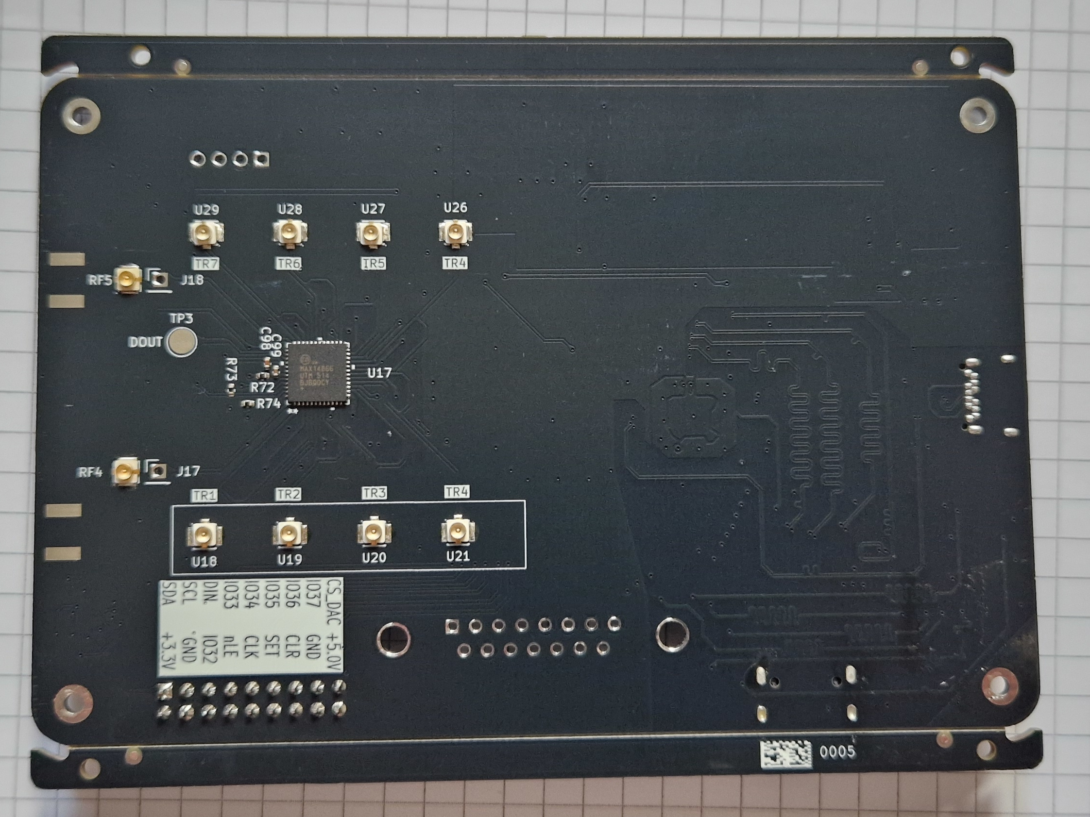
Mux bit n drives switch SWn. The switches are wired in pairs:
| Element | Connector | v0 silkscreen | RX switch (to the receiver) | TX switch (to the pulser) | TX+RX pattern |
|---|---|---|---|---|---|
| 1 | U18 | TR1 | SW0 | SW1 | 0x0003 |
| 2 | U19 | TR2 | SW2 | SW3 | 0x000C |
| 3 | U20 | TR3 | SW4 | SW5 | 0x0030 |
| 4 | U21 | TR4 | SW6 | SW7 | 0x00C0 |
| 5 | U26 | TR4 (wrong) | SW8 | SW9 | 0x0300 |
| 6 | U27 | TR5 (wrong) | SW10 | SW11 | 0x0C00 |
| 7 | U28 | TR6 (wrong) | SW12 | SW13 | 0x3000 |
| 8 | U29 | TR7 (wrong) | SW14 | SW15 | 0xC000 |
This comes from the netlist of hardware/MUX.kicad_sch: even COMs join MUX_IN (the receive input, ECHO_IN),
odd COMs join MUX_OUT (the pulser output, TX). The pulser output and the receiver input also go to the SMA edge
connectors PULSER_OUT (J1) and AFE_IN (J2), which don’t depend on the mux. The
back photo shows the element connectors.
dsp/dsp.c, dsp/pipeline.c)Core 1 processes each 4096-sample capture:
arm_rfft_fast_f32, 4096 points, float32.sqrt(real² + quadrature²), the envelope.dsp scale,
512 ADC counts by default).Each stage’s time is reported in status (stages_us=). The envelope takes about 6.55 ms (7.3 ms worst with
A-law). Only the float32 transform sources of CMSIS-DSP are compiled in.
Core 1 writes the result and its header into one of 2 output slots. If both slots are full, the frame is dropped and counted; the firmware never blocks.
main_dsp.c)Core 0 runs the USB task, parses commands, schedules streams, polls the capture and sends frames. Nothing on it may block. A USB disconnect cancels the session and disarms the pulser.
dsp/protocol.c)Every capture in the DSP build is sent as a 64-byte little-endian header followed by the payload:
| Field | Type | Notes |
|---|---|---|
| magic | 4 bytes | U4RK |
| version | u8 | protocol version, 1 |
| payload_type | u8 | 1 = raw (u16 per sample), 2 = envelope (f32), 3 = A-law (u8) |
| flags | u16 | bit 0 A-law saturated, 1 processing drop, 2 USB drop, 3 self-test, 4 pulser armed; bits 8+ self-test case |
| sequence | u32 | frame counter |
| sample_count | u32 | 8000 raw, 4096 envelope / A-law |
| sample_rate_hz | u32 | 60 000 000 |
| payload_bytes | u32 | |
| capture_timestamp_us | u64 | board time |
| adc_dc_mean | f32 | mean of the raw codes |
| envelope_peak | f32 | |
| alaw_reference | f32 | |
| negative_ns, damp_ns, positive_ns | 3 × u32 | pulse settings used |
| dropped_frames | u32 | |
| payload_crc32 | u32 | CRC32 of the payload |
If you change the header, change python/ultr4rick/dsp.py (HEADER, MAGIC) in the same commit.
Replies are one text line, OK <details> or ERR <CODE> <message> (BUSY, ARG, RANGE, RATE). Commands
that change settings answer ERR BUSY while a capture or stream is running.
| Command | Reply / effect |
|---|---|
help |
the command list |
status |
board=ultr4rick package=RP2350B firmware=… pulser=… pulse=… dac=… stream=… drops=… stages_us=… dsp_us=… |
version |
firmware version, change summary, board, mux, build hash, release URL (several lines) |
reboot-dfu |
reboots into the USB bootloader (RP2350 drive) |
pulser arm / pulser disarm |
arms / disarms the pulser |
pulse config <neg_ns> <damp_ns> <pos_ns> <neg-first\|pos-first> |
OK pulse=…, minimum 40 ns per phase |
dac write <0..1023> |
sets the receive gain, OK dac=… |
dsp scale <reference> |
A-law reference in ADC counts |
dsp selftest |
OK selftest frames=21 cases=7, then 21 frames (7 cases × raw / envelope / A-law) |
acq <raw\|envelope\|alaw> |
one capture: OK capture started …, then one frame |
read_raw / read_fft |
same as acq raw / acq envelope |
stream start <raw\|envelope\|alaw> <rate_hz> |
periodic frames until stream stop (only frames are sent while streaming) |
stream stop |
OK stream stopped drops=… |
write mux <hex> |
loads a 16-bit switch pattern, OK mux=… |
set mux / clear mux |
closes / opens all 16 switches |
| Command | Effect |
|---|---|
start acq [pon_ns] [poff_ns] [damp_ns] |
fires the pulser (positive first, defaults 200/200/2000) and captures 8000 samples |
read |
prints the last capture as hex values between Start of ACQ / End of ACQ lines |
write dac <0..1023> |
sets the receive gain |
write mux <hex>, set mux, clear mux |
as in the DSP build |
version, reboot-dfu |
as in the DSP build |
The LP5562 RGB LED (I2C0, GPIO24/25) shows what the firmware is doing, dimmed to 5%:
| Colour | Stage |
|---|---|
| white | booting |
| green | ready, idle |
| yellow | capture (and pulse) running |
| blue | core 1 computing a frame |
| magenta | frame being sent over USB |
| red | DMA fault (held briefly) |
The separate white LED (W channel) is on while a program has the serial port open.
See firmware/PINMAP.md. Short version: ADC clock GPIO0, data GPIO1–10, DAC CS GPIO11,
mux nLE/SET/CLR GPIO21/28/29, pulser A/B GPIO22/23, I2C0 GPIO24/25, SPI1 GPIO26/27, uSD GPIO30/31 and 40–43
(not used yet).
./build.sh -DPICO_TOOLCHAIN_PATH=/usr builds dist/ultr4rick-v<ver>-{ultr4rick,ultr4rick-dsp}.uf2.firmware/boards/ultr4rick.h: RP2350B, 12 MHz crystal, W25Q128 16 MiB flash.SPDX-License-Identifier: GPL-3.0-or-later (see LICENSE.md), except
pico_sdk_import.cmake, copied from the Pico SDK (BSD-3-Clause).version.yaml holds A.B.C and a one-line change summary, which are embedded in the binary. The history is in
firmware/CHANGELOG.md.